Description
Following on from the MIDI post, the project I am working on has a need for 3 Servo Motors to be controlled in much the same way as the lights. The final project will include lights and servos all controlled using MIDI.
The project is a ‘kinetic photo’ (remember where you saw that term first 🙂 ), though the techniques could be applied to displays for museums, stage productions, and art projects requiring synchronised operation but with something different to another computer based display.
Construction
This isn’t really a DIY post, but I’ll include the main components I used
What you’ll need:
– Arduino Uno or equivalent
– MIDI shield or equivalent
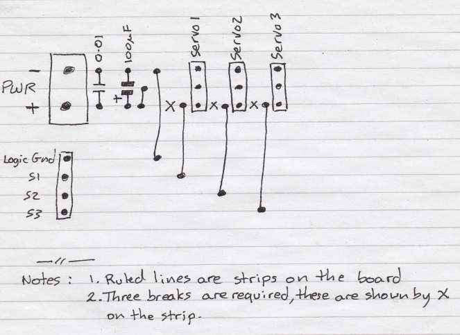
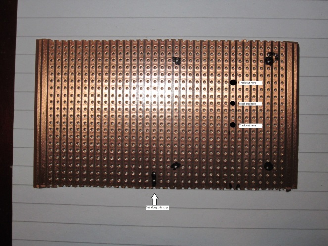
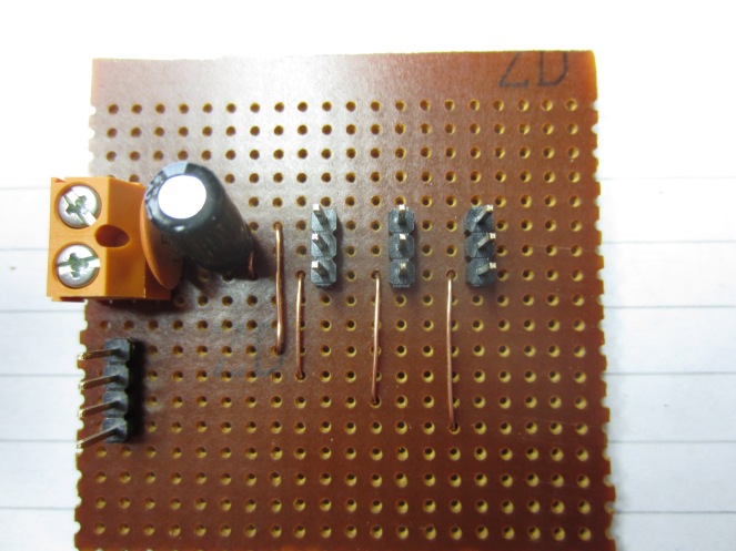
– Arduino to Servo interface, could be an off the shelf one, I made my own, see this post : https://myiot97.wordpress.com/2018/01/12/build-a-low-cost-3-way-arduino-servo-interface-with-external-power/
– 6V 2A Power supply recommended, if you are using a single small servo, it may work from the Arduino board
– Servo motors, with my interface, up to 3. If you extend the interface, or have multiple ones you could drive up to 10.
How it works
The MIDI interface code is the same as for the RGB light, but to save linking to that post, I’ll quote:
About MIDI
MIDI is short for “Musical Instrument Digital Interface”, it’s a simple control standard for musical instruments that was developed in the 1980s, but has become a very widely used standard for synchronisation and control of electronic musical instruments, effects unit and other equipment, for example scenery or effects queues on stage.
I’m not going to go into the full details as this project only uses a subset of MIDI’s capabilities, but I will briefly describe the elements relevant to this project. The standard defines three aspects, the physical interface, the data communication standard, and the data format.
The physical interface is an optically isolated current loop connected using 5 pin DIN connections, each connector is uni-directional (ie can only send or receive, but not both), with most devices having an “input” connector, and an “output” connector. Some devices also have a “through” connector which passes the data on the input connector to the next device, thus allowing devices to be cascaded. In the audio world, the optical isolation helps avoid earth loop problems, it also helps prevent accidentally frying equipment as you plug it in and unplugging it.
The data communication standard is asynchronous, 31250 bps, 8 bits, no parity, 1 stop, which, may seem like an odd bit rate, the historical reason is it is simple to generate with a 1MHz processor clock which was common when MIDI was developed, the Arduino’s inbuilt USART does it with ease.
The data format consists of commands and data, distinguishable by the MSB of bytes sent over the link, so:
Byte Type
0x00-0x7F Data
0x80-0xFF Command
Commands can be followed by one or two data bytes.
Between 0x80 and 0xEF, the low order Hex character is called the MIDI Channel, and is typically used to select the device that the command is directed at, so the MIDI standard permits up to 16 devices to be addressed, though more devices may be present if they share the same Channel number, but that will affect how they interact. For the purpose of this post, I will be referring to commands as 0x0n to 0xEn, where n is the Channel.
Commands numbered 0xF0 to 0xFF do not have a MIDI channel, and therefore apply to all devices, although how each device interprets them may be different, so that is getting into the murky, dirty secret of MIDI, and that’s the last I will mention it.
For this project, there are only two commands of interest, called “Note On” and “Note Off”, each of which is followed by two data bytes, Note and Velocity.
Note is fairly self-explanatory, it refers to the note on the keyboard.
Velocity is the speed or force that the key was pressed or released, for musical instruments it is used to provide expression, how loud, or in the case of piano, also how harsh the note plays. For control systems, eg a light, it can determine the brightness or other parameters depending on the application.
Action Command Note Velocity
Note on 0x90 0x00-0x7F 0x00-0x7F
Note off 0x80 0x00-0x7F 0x00-0x7F
For full details, please refer to https://en.wikipedia.org/wiki/MIDI.
What this project does
This project allows one of ten servo motors to be controlled by MIDI. Each motor is assigned a different note, though chords allow combinations of the motors. The velocity of each note determines the angle that the servo moves to from 0 to 180
If that seems a bit hard to get your head around, I have produced a video to demonstrate it:
Connecting it up
The MIDI shield I used does not pass-through the connections from the Arduino base board, instead it routes them to a set of headers. If yours does the same, you will need to work out which pins to use to connect to the servo.
The MID shield shares the serial port used for programming the Arduino, in order to prevent conflicts, it should have an on-off switch, or a header. When programming the Arduino, this will need to be in the off position. When using the MIDI interface, it will need to be on.
About the code
The MIDI portion of the program is the same as for the RGB LED, but the motor control changes.
I started by trying to use the pulse width modulation outputs as for the tri-colour LED. The low torque servos worked reasonably well, but the high torque one went a bit crazy.
I switched to using the Arduino Servo Library (See https://www.arduino.cc/en/Reference/Servo)
As a bonus, the servo library can make any digital pin drive a servo, not just the PWM pins, with the MIDI interface, that means it could control up to 10 servos, as two pins are used by the MIDI interface. Of course you can still use the PWM pins to control LEDs, with the other digital pins controlling servo motors. But a pin can’ be used for both servo and the inbuilt PWM at the same time.
The code
/*
* MIDI Servo core code.
*/
#include <Servo.h>
// MIDI Command codes, note, the low order 4 bits are 0
#define MIDI_Note_Off 0x80
#define MIDI_Note_On 0x90
// MIDI in read actions
#define WAIT 1 // Waiting for a valid MIDI command.
#define Note_Off 2 // MIDI_Note_Off was received.
#define Note_On 3 // MIDI_Note_On was received.
// Output pins
#define Servo1 9
#define Servo2 10
#define Servo3 11
Servo myservo1; // create servo object to control a servo
Servo myservo2; // create servo object to control a servo
Servo myservo3; // create servo object to control a servo
int pos = 0; // variable to store the servo position
//
// MIDI Reception variables
byte IncomingByte; // Byte from serial port
byte MIDI_Command; // undecoded MIDI command (0xn0, where n=0x8 to 0xF)
byte MIDI_Channel; // MIDI Channel (0x00 to 0x0F)
int action = WAIT; // Decoded MIDI Command
byte note = 0x80; // Initialised to invalid note.
byte velocity = 0; //
void setup() {
// Configure the serial port for MIDI, which is 31250 bps, 8 bits, no parity, 1 stop.
Serial.begin(31250);
// Configure the output pins
myservo1.attach(Servo1); // attaches the servo on pin 9 to the servo object
myservo2.attach(Servo2); // attaches the servo on pin 9 to the servo object
myservo3.attach(Servo3); // attaches the servo on pin 9 to the servo object
// Initial servo test, full rotation test for each servo
for (pos = 0; pos <= 180; pos += 1) { // goes from 0 degrees to 180 degrees
// in steps of 1 degree
myservo1.write(pos); // tell servo to go to position in variable ‘pos’
delay(15); // waits 15ms for the servo to reach the position
}
for (pos = 180; pos >= 0; pos -= 1) { // goes from 180 degrees to 0 degrees
myservo1.write(pos); // tell servo to go to position in variable ‘pos’
delay(15); // waits 15ms for the servo to reach the position
}
for (pos = 0; pos <= 180; pos += 1) { // goes from 0 degrees to 180 degrees
// in steps of 1 degree
myservo2.write(pos); // tell servo to go to position in variable ‘pos’
delay(15); // waits 15ms for the servo to reach the position
}
for (pos = 180; pos >= 0; pos -= 1) { // goes from 180 degrees to 0 degrees
myservo2.write(pos); // tell servo to go to position in variable ‘pos’
delay(15); // waits 15ms for the servo to reach the position
}
for (pos = 0; pos <= 180; pos += 1) { // goes from 0 degrees to 180 degrees
// in steps of 1 degree
myservo3.write(pos); // tell servo to go to position in variable ‘pos’
delay(15); // waits 15ms for the servo to reach the position
}
for (pos = 180; pos >= 0; pos -= 1) { // goes from 180 degrees to 0 degrees
myservo3.write(pos); // tell servo to go to position in variable ‘pos’
delay(15); // waits 15ms for the servo to reach the position
}
myservo1.write(90);
myservo2.write(90);
myservo3.write(90);
}
void loop() {
if (Serial.available() > 0) {
// read the incoming byte:
IncomingByte = Serial.read();
MIDI_Command = IncomingByte & 0xF0;
MIDI_Channel = IncomingByte & 0x0F;
// Was it a MIDI command (bit 7 = 1)?
if (bitRead(MIDI_Command, 7) == 1) {
// If so, need to save the decoded action & reset note and velocity
switch (MIDI_Command){
case MIDI_Note_On:
action = Note_On;
break;
case MIDI_Note_Off:
action = Note_Off;
break;
}
note = 0x80;
velocity = 0;
}
else {
// Process data byte
if (note == 0x80 && action != WAIT) // note on, wait for note value
{
note = IncomingByte;
}
else if (note != 0x80 && action != WAIT) // velocity
{
velocity = IncomingByte;
// All elements of the command have been received, now process it.
if (action == Note_On) {
Set_Servo(MIDI_Channel, note, velocity);
}
else if (action == Note_Off) {
Reset_Servo(MIDI_Channel, note);
}
note = 0x80;
velocity = 0;
action = WAIT;
}
}
}
}
void Set_Servo(byte MIDI_Channel, byte Note, byte Velocity) {
// This function is the one you will most likely need to change to adapt this project to different applications.
//
// As this is test code, I have avoided making it too fancy, so Bit 0 drives servo1, Bit 1 drives servo2 and Bit 2 drives servo3.
// The Velocity value determines the value.
// As the approach is bitwise, a single key may set more than one of the servos
//
pos = map(Velocity, 1, 127, 0, 179);
if((Note & 1)!=0){
myservo1.write(pos);
}
if((Note & 2)!=0){
myservo2.write(pos);
}
if((Note & 4)!=0){
myservo3.write(pos);
}
}
void Reset_Servo(byte MIDI_Channel, byte Note) {
// This function is one you will most likely need to change to adapt this project to different applications.
//
// When the midi key is released, this function is called and may be used to reset the servo to it’s home.
//
pos = 89; //By default, home is the servo’s 90degree mark.
if((Note & 1)!=0){
myservo1.write(pos);
}
if((Note & 2)!=0){
myservo2.write(pos);
}
if((Note & 4)!=0){
myservo3.write(pos);
}
}